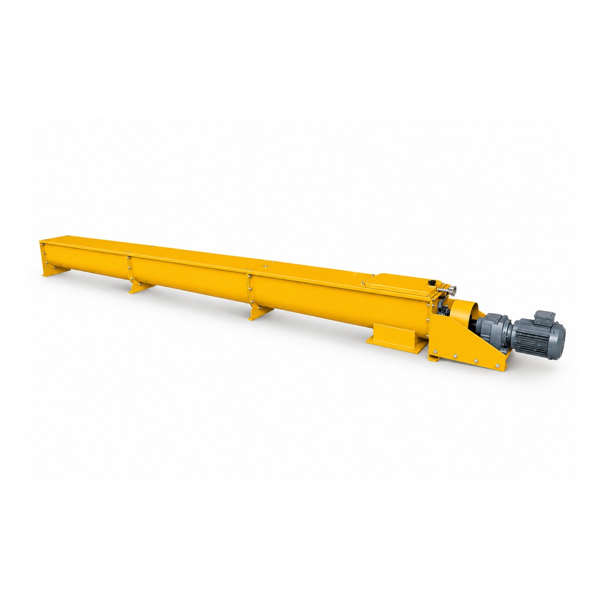
TLSS Screw Conveyor
Transfers grain and flour through a screw conveyor body. Six size ranges cover different material flows and drive requirements.
Specifications and configurations
| Model | Capacity (t/h) | Power (kW) |
|---|---|---|
| TLSS160 | 2–6 | 0.75–1.5 |
| TLSS200 | 4–12 | 1.5–3 |
| TLSS250 | 7.5–23 | 1.5–4 |
| TLSS300 | 13–37 | 3.0–4 |
| TLSS400 | 20–53 | 3.0–5.5 |
| TLSS500 | 25–75 | 5.5–11 |
Capacity depends on speed, fill and material; see the 83 r/min configuration below for a fixed-speed reference.
On small screens, scroll the table to see all specifications.
Variable-speed TLSS configuration
Select speed and drive for the material and conveying length. Power and length ranges are configuration data, not a capacity guarantee.
| Model | Screw Ø (mm) | Pitch (mm) | Speed (r/min) | Conveying length (m) | Power (kW) |
|---|---|---|---|---|---|
| TLSS16 | 160 | 130 | 60–160 | 25 | 0.75–2.2 |
| TLSS20 | 200 | 160 | 65–140 | 25 | 0.75–3.0 |
| TLSS25 | 250 | 200 | 65–130 | 30 | 1.1–4.0 |
| TLSS32 | 320 | 250 | 65–110 | 35 | 1.5–5.5 |
| TLSS40 | 400 | 320 | 50–100 | 35 | 2.2–7.5 |
| TLSS50 | 500 | 400 | 50–90 | 35 | 3.0–11 |
TLSS configuration at 83 r/min
This is a separate configuration. Its capacity data must not be combined with the power ranges in the table above.
| Model | Blade Ø (mm) | Maximum lead (mm) | Speed (r/min) | Capacity (t/h) | Blade clearance (mm) |
|---|---|---|---|---|---|
| TLSS16 | 160 | 130 | 83 | 1–2 | 10 |
| TLSS20 | 200 | 160 | 83 | 2–3 | 10 |
| TLSS25 | 250 | 200 | 83 | 3–4 | 10 |
| TLSS32 | 320 | 260 | 83 | 5–8 | 10 |
| TLSS40 | 400 | 320 | 83 | 10–12 | 10 |
Choose for the operating duty
Send material, bulk density, required flow, conveyor length and inclination. Specify every inlet and outlet; route length and load affect motor selection.
- Six sizes from TLSS160 to TLSS500.
- Capacity and power are given as configuration ranges.
- Lay out the conveying route and inspection access together.
Plan the installation
Material and duty
Describe material, bulk density, normal flow and peak demand.
Layout
Include inlet and outlet positions, elevation changes and maintenance access.
Supports
Provide the supporting structure and connection drawings for replacement equipment.
Utilities
State voltage, frequency and any compressed-air or control-system requirements.
Existing equipment and spare parts
For a replacement, send the nameplate, a photograph, connection dimensions and the required duty. For individual parts, include dimensions and the machine serial number.
Explore spare partsDiscuss your requirements
Send material, bulk density, required flow, conveyor length and inclination. Specify every inlet and outlet; route length and load affect motor selection.
WhatsApp Farivo